IGCSE Physics Electricity Past Papers Exam Questions (Edexcel): 2019-22
We analysed the International GCSE past papers and grouped the questions by topic. Here, you will find questions relating to the topic – Electricity. Use these to familiarise, practice and prepare for your IGCSE Physics examination.
What you need to know
Use the list below as a quick recap for what you need to know before attempting the past year exam questions under this topic. This is based on Edexcel International GCSE in Physics (4PH1) specification with first teaching Sept 2017 and first examination June 2019.
Paper 1 and 2: (2) Electricity
Paper 1 covers the Electricity topics below except “Electric charge” while paper 2 covers all Electricity topics.
A. Units
- electrical units: ampere (A), coulomb (C), joule (J), ohm (Ω), second (s), volt (V) and watt (W).
B. Mains electricity
- use of insulation, earthing, fuses and circuit breakers.
- why current in a resistor results in transfer of energy and increase in temperature.
- power = current x voltage. P=I×V
- energy transferred = current x voltage x time. E=I×Vxt
- the difference between alternating (ac) and direct currents (dc).
- explain the use of parallel and series circuits
C. Energy and voltage in circuits
- how the current in a series circuit depends on the applied voltage and the nature of components in the circuit.
- describe and investigate how current varies with voltage in wires, resistors, filament lamps and diodes.
- describe the qualitative effect on current of changing the resistance in the circuit.
- describe the variation of light-dependent resistors with light intensity
- and thermistors with temperature.
- lamps and LEDs show the presence of a current in a circuit.
- voltage = current x resistance. V=I×R
- current is the rate of flow of charge
- current = current x time. Q=I×t
- electric current in solid metallic conductors is a flow of negatively charged electrons
- why current is conserved at a junction
- voltage across two components in parallel is the same
- calculate the currents, voltages and resistances of two resistive components connected in a series circuit
- voltage is the energy transferred per unit charge (joule per coulomb)
- energy transferred = charge x voltage. E=Q×V
D. Electric charge (paper 2 only)
- identify common materials that are insulators and conductors (metals and plastics)
- practical: how insulating materials can be charge by friction
- explain the charging of materials by the loss (+ve electrostatic charge) or gain of electrons (-ve electrostatic charge)
- that there are attractive forces between unlike charges and repulsive forces between like charges
- explain the potential dangers of electrostatic charges (fuelling aircraft and tankers)
- explain some uses of electrostatic charges (photocopiers and inkjet printers)
June 2019 Paper 1
6 (a) (i) A student investigates how current varies with voltage for a metal filament lamp.
Draw a diagram of the circuit that a student could use for this investigation.(4)
(ii) Describe a method the student could use for their investigation.(4)
(b) The student extends the investigation by recording additional data for the lamp.
This is her method.
For each voltage
- switch the current on for 45 seconds
- record the current and colour of the lamp
- calculate the power and the energy transferred by the lamp
The table shows the student’s results.
| Voltage in V | Current | Power in W | Energy in J | Colour of lamp |
| 0.0 | 0.0 | 0.0 | 0.0 | off |
| 2.0 | 0.40 | 0.8 | 35 | red |
| 4.0 | 0.90 | 3.6 | orange | |
| 6.0 | 1.60 | 9.6 | 430 | yellow |
| 8.0 | 2.80 | 22.4 | 1000 | white |
(i) State the unit for current.(1)
(ii) Calculate the missing value of energy for the voltage of 4.0 V (2)
Give your answer to 2 significant figures.
energy = ……………………………..J
(iii) The colour of a star is related to its surface temperature.
The Sun is yellow.
Use the student’s results to identify a colour for a star that is cooler than the Sun.(1)
June 2019 Paper 1
10 This question is about voltage and current. The diagram shows two resistors connected to a battery.
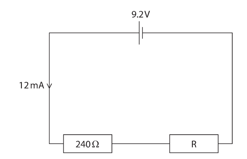
Calculate the voltage across resistor R.(4)
voltage = ……………………………V
(b) The diagram shows the parts of an ammeter.
The pointer is connected to the coil so they can move together.
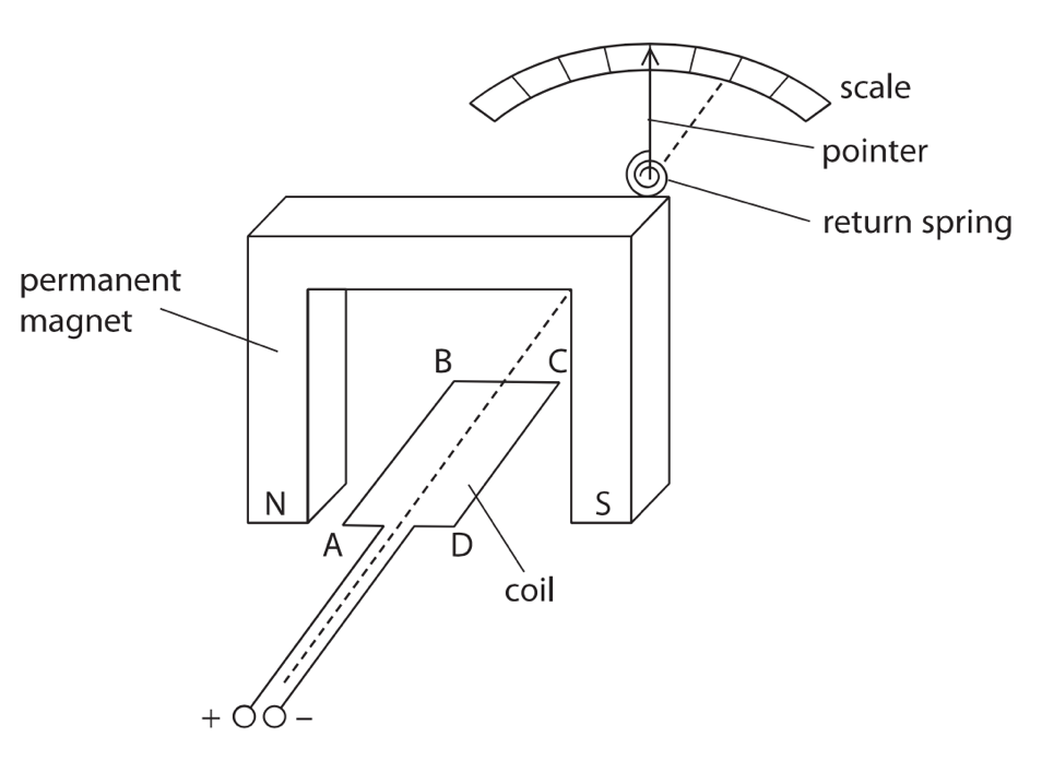
(i) Explain what happens when there is a current in the coil. (3)
(ii) Drawn an arrow on the diagram to show the force acting on side CD of the coil when there is a current in the coil. (1)
(iii) Explain how the ammeter could be changed so that it could measure smaller currents.(3)
Total for Question 10 = 11 marks
June 2019 Paper 1PR
5. A student is given a type of putty that conducts electricity.
He rolls the putty into cylinders of different cross-sectional area.
The photograph shows the cylinders.
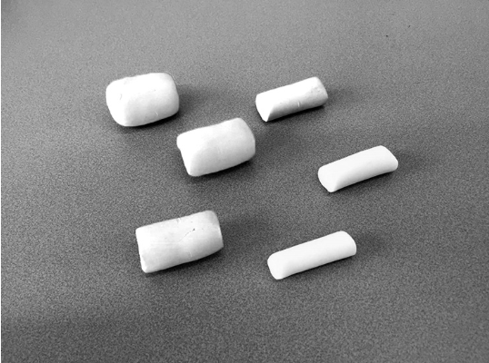
The student investigates how the electrical resistance of the putty is affected by its cross-sectional area.
(a) The diagram shows the cross-sectional area of one of the cylinders of putty.
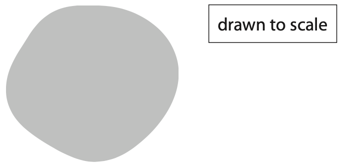
(i) Use the diagram to determine the mean diameter of the cylinder of putty. (2)
mean diameter = ……………………………………….. cm
(ii) Calculate the cross-sectional area of the cylinder of putty in cm2. (2)
[area of a circle = π × radius2]
cross-sectional area = ……………………………………….. cm2
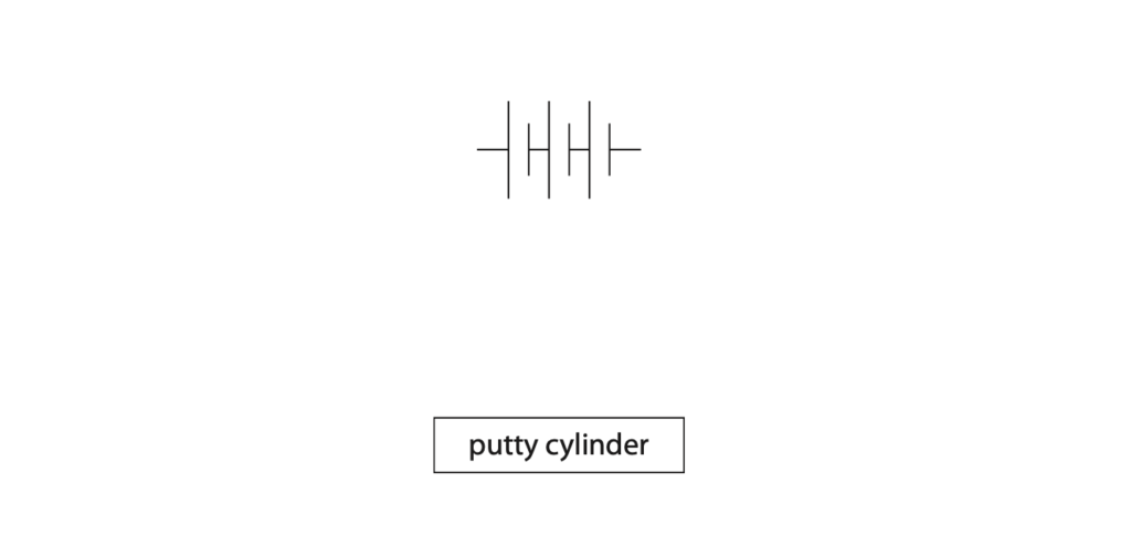
(b) The student connects a cylinder of putty to a battery.
He measures the voltage of the cylinder and the current in the circuit.
Complete the circuit diagram, adding suitable instruments to measure the voltage of the cylinder and the current in the circuit. (3)
(c) The student uses his voltage and current measurements to calculate the resistance of this cylinder.
He repeats this for other cylinders.
The table shows some of his results.
| Cross-sectional area in cm2 | Voltage in V | Current in A | Resistance in Ω |
| 4.5 | 4.56 | 0.049 | 91.2 |
| 6.2 | 4.56 | 0.059 | 77.3 |
| 9.1 | 4.56 | 0.068 | 67.1 |
| 13.9 | 4.56 | 0.085 | 53.6 |
| 18.1 | 4.56 | 0.094 | 48.5 |
| 24.6 | 4.56 | 0.107 |
(i) Calculate the resistance of the cylinder when the cross-sectional area of the cylinder is 24.6 cm2.
Give your answer to 3 significant figures. (2)
resistance = ……………………………………….. Ω
(ii) Plot a graph of resistance on the y-axis and cross-sectional area on the x-axis. (3)
(iii) Draw the curve of best fit. (1)

(d) The student extends his investigation by connecting two new identical cylinders to a battery.
The diagram shows the circuit he uses.
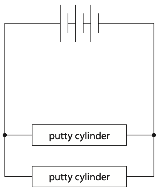
He measures the voltage of each cylinder and the total current in the circuit.
Discuss how his measurements of voltage and current compare with the measurements when only one of these cylinders is used. (4)
(Total for Question 5 = 17 marks)
June 2019 Paper 2P
2. A student investigates a transformer.
This is the student’s method.
- use a primary coil with 10 turns
- connect the primary coil to a constant maximum input voltage
- measure the output voltage across the secondary coil
- repeat using an increasing number of turns on the primary coil
The table shows the student’s results.
| Number of turns on primary coil | Output voltage in V |
| 10 | 39.6 |
| 20 | 19.7 |
| 40 | 9.9 |
| 60 | 6.6 |
| 80 | 5.0 |
| 100 | 4.0 |
(a) (i) Plot a graph of the student’s results on the grid. (1)
(ii) Draw a curve of best fit. (1)
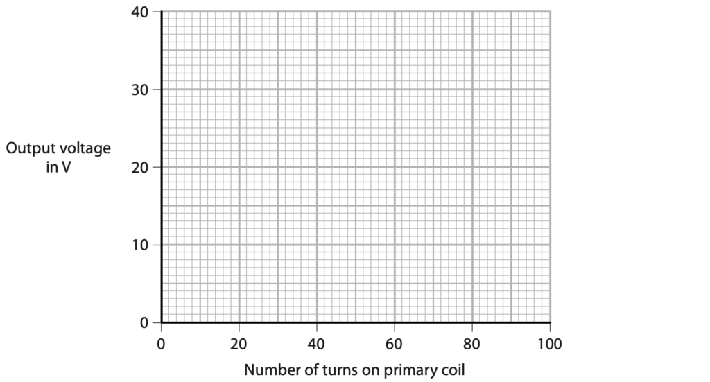
(iii) Describe the relationship between the output voltage and the number of turns on the primary coil. (2)
(b) (i) State the formula linking input and output voltages and the turns ratio for the transformer. (1)
(ii) The input voltage of the transformer is 6.8 V.
Calculate the number of turns on the secondary coil. (2)
number of turns = …………………………………………………….
(Total for Question 2 = 7 marks)
June 2019 Paper 2PR
3 (a) A student charges a plastic rod by rubbing it with a cloth.
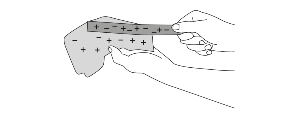
The rod becomes negatively charged.
(i) Which statement explains how the rod becomes negatively charged? (1)
A the rod gains positively charged electrons
B the rod loses positively charged electrons
C the rod gains negatively charged electrons
D the rod loses negatively charged electrons
(ii) Describe how the student could demonstrate that the rod is charged. (2)
(b) The student has several other rods made from different kinds of plastic.
Some rods can be charged positively and some can be charged negatively.
Describe an experiment to show that different rods have different types of charge.
You may draw a diagram to help your answer. (3)
(Total for Question 3 = 6 marks)
January 2020 Paper 1
3 This question is about electric circuits.
(a) Which quantity is defined as the rate of flow of charge? (1)
A current
B power
C resistance
D voltage
(b) Which quantity is defined as the energy transferred per unit charge passed? (2)
A current
B power
C resistance
D voltage
(c) Diagram 1 shows an electric circuit with two resistors, R and S.
Some of the values of the current are also shown.
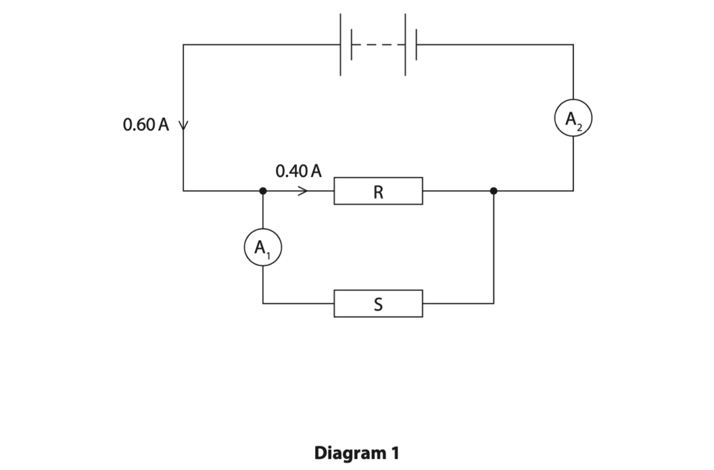
(i) On Diagram 1, draw a voltmeter to measure the voltage of resistor S. (2)
(ii) Deduce the readings on the ammeters. (2)
current measured by A1 = …………………………………………………….. A
current measured by A2 = …………………………………………………….. A
(iii) Resistor R has a resistance of 11 Ω.
Calculate the voltage across resistor R (3)
voltage = …………………………………………………….. V
(iv) Explain how the voltage across resistor R compares with the voltage across the battery. (2)
(d) Diagram 2 shows a different circuit containing a battery, an ammeter and a thermistor.
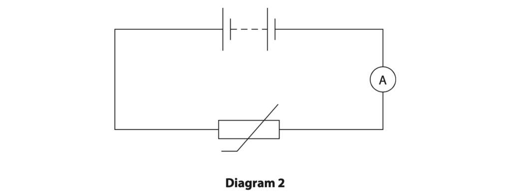
Explain how the thermistor can be used to vary the current in this circuit. (3)
(Total for Question 3 = 14 marks)
January 2020 Paper 1PR
6 The circuit diagram shows a light dependent resistor (LDR) and a 73 Ω resistor connected in series with a 1.5V cell.
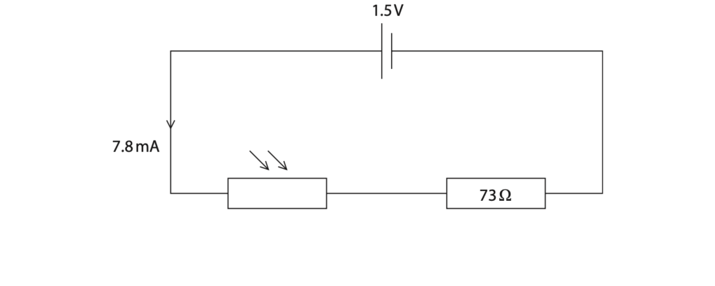
(a) Complete the diagram by adding an instrument to measure the voltage of the LDR. (2)
(b) (i) State the formula linking voltage, current and resistance. (1)
(ii) The current in the circuit is 7.8 mA.
Calculate the voltage across the 73 ohm resistor. (2)
voltage across resistor = …………………………………………………….. V
(iii) Calculate the voltage across the LDR. (2)
voltage across LDR = …………………………………………………….. V
(c) The graph shows how the resistance of the LDR changes with light intensity.

(i) Describe the relationship between the resistance of the LDR and light intensity. (2)
(ii) The resistance of the LDR decreases.
State the effect on the current in the circuit. (1)
(iii) Explain why the voltage across the LDR decreases when the resistance of the LDR decreases. (2)
(Total for Question 6 = 12 marks)
January 2020 Paper 1PR
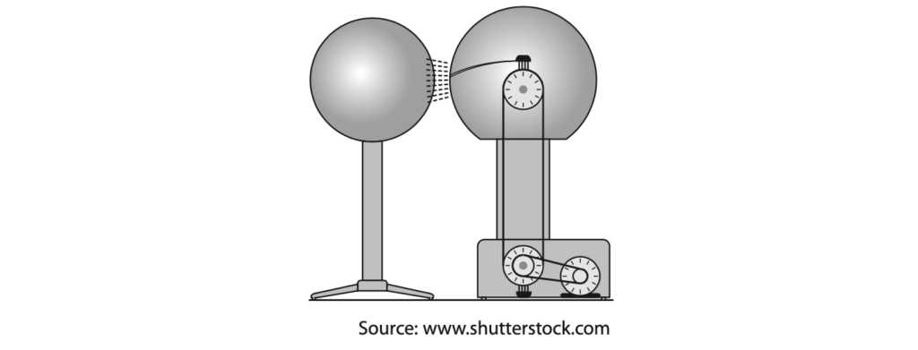
7 The diagram shows a van der Graaff generator, which is designed to provide very high voltages.
(a) (i) The unit of voltage is the volt.
Which of these units is a volt? (1)
- A coulomb per second
- B joule per coulomb
- C joule per second
- D newton per coulomb
(ii) State the formula linking energy transferred, voltage and charge. (1)
(iii) Calculate the energy transferred to an electron when it passes through a voltage of 150 kV. (3)
[charge of electron = 1.6 × 10⁻¹⁹ C]
energy transferred = …………………………………………………….. J
(b) When the van der Graaff generator is fully charged, it stores 2.9 × 10⁻⁸ C of charge.
(i) State the formula linking charge, current and time. (1)
(ii) The charge on the generator discharges through the air as a spark.
The charge takes a time of 0.68 ms to leave the generator.
Calculate the mean (average) current in the air. (3)
mean current = …………………………………………………….. A
Total for Question 7 = 9 marks
January 2020 Paper 2P
4 A student uses this apparatus to demonstrate the effect of electric charge.
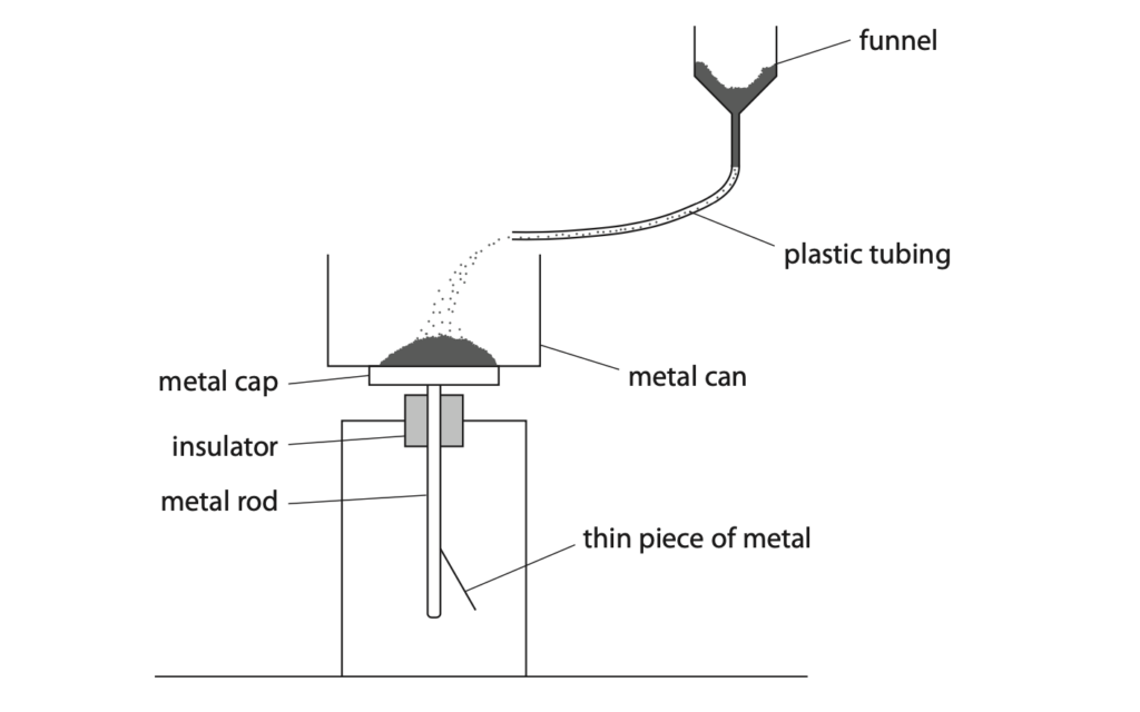
He pours some fine powder into a funnel.
The fine powder moves through a length of plastic tubing and falls into a metal can.
The metal can rests on a metal cap.
The metal cap is connected to a thin piece of metal via a metal rod.
When the powder lands in the can, the thin piece of metal moves away from the metal rod.
(a) Explain why the thin piece of metal moves away from the metal rod. (4)
(b) A coulombmeter measures electric charge.
The student connects a coulombmeter to the metal can.
When all the powder has landed in the can, the coulombmeter shows a readingof–9.4×10⁻⁹ C.
(i) Which statement is true for the metal can? (1)
A it gains negatively charged electrons
B it loses negatively charged electrons
C it gains positively charged electrons
D it loses positively charged electrons
(ii) State the formula linking charge, current and time. (1)
(iii) It takes a time of 12 s from when the powder starts landing in the metal can until all the powder has landed in the can.
Calculate the mean charging current. (3)
current = …………………………………………………….. A
(c) The student suggests that this demonstration is similar to refuelling an aircraft.
The powder represents the fuel and the metal can represents the fuel tank in the aircraft.
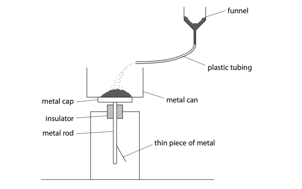
Explain how the student should modify this apparatus to demonstrate how to minimise the dangers when refuelling an aircraft.
You may add to the diagram to help your answer. (3)
(Total for Question 4 = 12 marks)
June 2020 Paper 1P
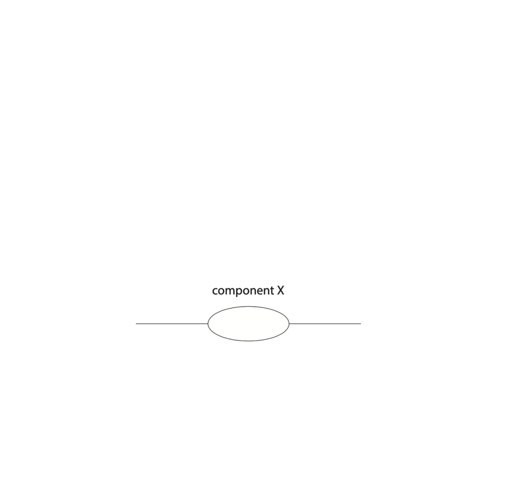
5 A student does an investigation to determine the current-voltage graph for an unknown component, X.
The student uses this equipment
- component X
- cell
- variable resistor
- ammeter
- voltmeter
- connecting wires
(a) Complete the circuit diagram to show how the student should set up this equipment for her investigation. (4)
(b) The student completes her investigation.
The table shows her results.
| Voltage in V | Current in mA |
| 0.00 | 0 |
| 0.10 | 0 |
| 0.20 | 0 |
| 0.30 | 0 |
| 0.40 | 0 |
| 0.50 | 2 |
| 0.60 | 8 |
| 0.70 | 33 |
| 0.80 | 140 |
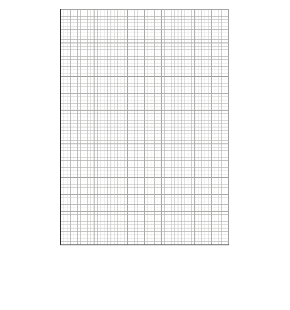
(i) Plot a graph of the student’s results on the grid.
Plot current on the y-axis and voltage on the x-axis. (3)
(ii) Draw a curve of best fit. (1)
(iii) State the name of component X. (1)
(Total for Question 5 = 9 marks)
June 2020 Paper 1P
6 The diagram shows an electric circuit.
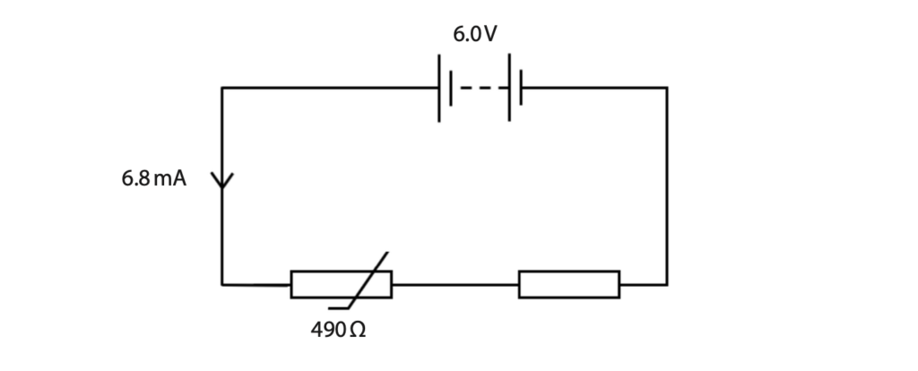
(a) When the thermistor is in hot water, its resistance is 490 Ω.
Show that the resistance of the fixed resistor is about 400 Ω. (5)
(b) Explain how the voltage across the fixed resistor changes when the hot water is replaced with cold water. (3)
(Total for Question 6 = 8 marks)
June 2020 Paper 1PR
8 A student uses this apparatus to investigate how the efficiency of an electric motor varies with its input voltage.
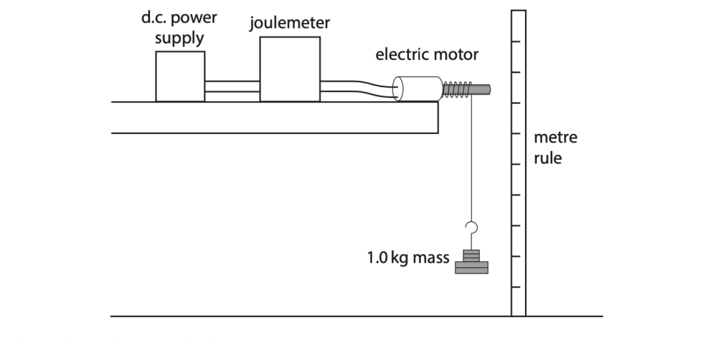
This is the student’s method.
- connect the electric motor to a d.c. power supply and a joulemeter
- attach a 1.0 kg mass to the electric motor using a length of string
- set the voltage of the power supply to 10V and switch on the power supply
- switch off the power supply when the mass has been lifted through a distance of 50 cm
- record the input energy to the motor from the joulemeter
- calculate the energy transferred to the gravitational store of the mass
- calculate the efficiency of the motor
The student repeats this process, setting the power supply to a different voltage each time.
(a) State how the student could improve the reliability of her results. (1)
(b) Give two control variables for the investigation. (2)
1.
2.
(c) Show that the gravitational store of the 1.0 kg mass increases by 5.0 J when it is lifted through a distance of 50 cm. (2)
(d) The table shows the student’s results.
| Power supply voltage in V | Joulemeter reading in J | Motor efficiency (%) |
| 3.0 | 99.4 | 5.0 |
| 3.5 | 25.5 | 19.6 |
| 4.0 | 16.5 | 30.3 |
| 5.0 | 13.5 | 37.0 |
| 6.0 | 12.6 | 39.7 |
| 8.0 | 12.8 | 39.1 |
| 10.0 | 12.7 |
(i) Calculate the motor efficiency when the power supply is set to a voltage of 10V. (3)
efficiency = ……………………………………………………………………….. %
(ii) Plot a graph of the motor efficiency on the y-axis against the power supply voltage on the x-axis. (3)

(iii) Draw a curve of best fit. (2)
(iv) Using the graph, determine the minimum power supply voltage that will allow the electric motor to operate at maximum efficiency. (1)
power supply voltage = ……………………………………………………………………….. V
(Total for Question 8 = 14 marks)
June 2020 Paper 1PR
9 The diagram shows part of a circuit used for an outdoor lighting system.
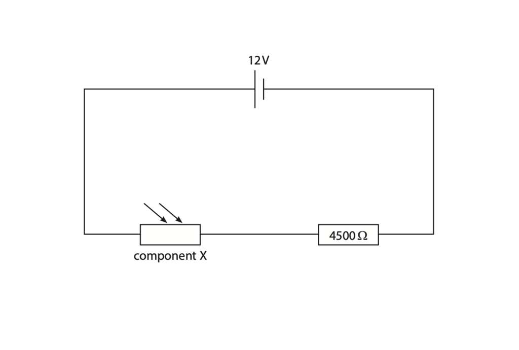
(a) Draw a voltmeter on the diagram to measure the voltage of the 4500 Ω resistor.(2)
(b) Give the name of component X. (1)
(c) The voltage across component X is 3.0V.
(i) Calculate the voltage across the 4500 Ω resistor. (1)
voltage = ……………………………………………………………………….. V
(ii) Calculate the current in the circuit. (2)
[voltage = current × resistance]
current = ……………………………………………………………………….. A
(iii) Calculate the resistance of component X. (3)
Give your answer in kΩ.
resistance = ……………………………………………………………………….. kΩ
(d) Explain where a lamp should be connected in this circuit, so that the voltage across it increases as the light received by component X decreases.(3)
(Total for Question 9 = 12 marks)
June 2020 Paper 2P
2 This question is about a demonstration to show the link between current and charge.
The diagram shows two metal plates, X and Y, with a metal ball moving between them.
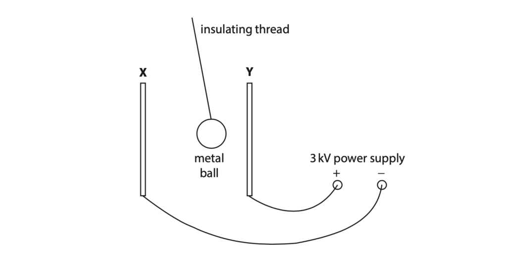
(a) The two metal plates have no charge before the power supply is connected.
When plate Y is connected to the positive terminal of the power supply, the plate becomes positively charged.
Explain how plate Y gains a positive charge. (2)
(b) (i) The metal ball becomes positively charged when it touches plate Y.
The metal ball then moves away from plate Y towards plate X.
Explain why the metal ball moves away from plate Y.
(ii) Give a reason why the ball is made of metal. (1)
(c) When the metal ball moves away from plateY to plate X, a charge of 5.1×10⁻⁶C is transferred.
(i) State the formula linking charge transferred, current and time taken. (1)
(ii) Calculate the current if the metal ball takes 0.45 seconds to travel from plate Y to plate X. (2)
current = …………………………………………………. A
(iii) Suggest why the current increases if the voltage of the power supply is increased. (1)
(iv) Give the name of the apparatus that can be used to measure current. (1)
(Total for Question 2 = 10 marks)
June 2020 Paper 2PR
1 This question is about electrostatics.
(a) A student uses a plastic rod to investigate electrostatics.

(i) Describe how the student could have charged the plastic rod. (2)
(ii) The student uses a meter to measure the amount of charge on the rod.
The meter displays a reading of –5.2 mC.
Which of these is the same as –5.2 mC? (1)
A –0.52 C
B –0.052 C
C –0.0052 C
D –0.00052 C
(iii) The rod is negatively charged.
Which statement correctly explains why the rod is negatively charged? (1)
A the rod has gained negatively charged electrons
B the rod has gained positively charged electrons
C the rod has lost negatively charged electrons
D the rod has lost positively charged electrons
(iv) Using a meter is one method of demonstrating that the rod is charged.
Describe another method of demonstrating that the rod is charged. (2)
(b) Electrostatic charges can be useful but they can also be dangerous.
(i) Give one use of electrostatic charges. (1)
(ii) Explain why electrostatic charges can be dangerous when fuelling an aeroplane. (2)
(Total for Question 1 = 9 marks)
January 2021 Paper 1P
3 The photograph shows a mains-operated, decorative lamp, X.
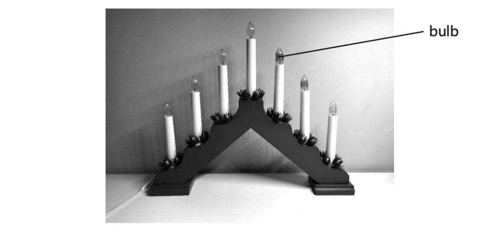
Lamp X has seven identical bulbs that are connected in series.
(a) Give a disadvantage of connecting the bulbs in series. (1)
(b) Suggest an advantage of connecting the bulbs in series. (1)
(c) Each bulb has a working resistance of 390Ω.
The voltage across each bulb is 33V.
(i) State the formula linking voltage, current and resistance. (1)
(ii) Calculate the current in each bulb. (3)
current = …………………………………………………… A
(iii) Calculate the energy transferred to lamp X when it is used for 2.5 hours. (4)
energy transferred = …………………………………………………… J
(d) Another decorative lamp, Y, uses five of the same 390 Ω bulbs connected in series.
Both lamps are mains operated.
Explain how the brightness of a single bulb in lamp Y compares to the brightness of a single bulb in lamp X. (3)
(Total for Question 3 = 13 marks)
January 2021 Paper 1P
4 The photograph shows a hair dryer plugged into the mains supply.
The hair dryer contains a fuse.
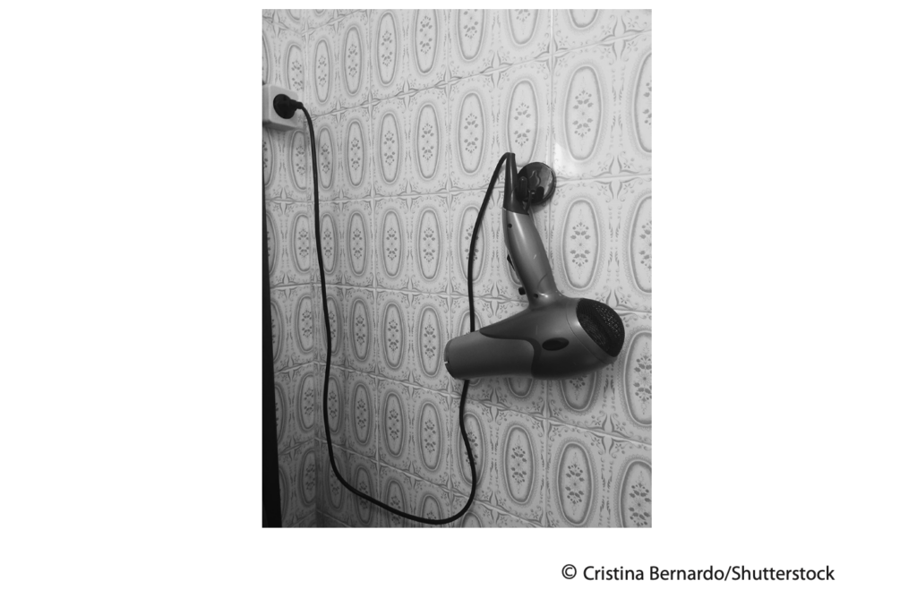
(a) State which wire in the hair dryer should be in series with the fuse. (1)
(b) The fuse is an electrical safety feature used in mains-operated domestic appliances.
State two other electrical safety features that can be used in mains-operated domestic appliances. (2)
1
2
(c) The hair dryer has a current of 9.6A.
The mains supply voltage is 230V.
(i) State the formula linking power, current and voltage. (1)
(ii) Calculate the power of the hair dryer. (3)
Give the unit.
power = …………………………………………………… unit ……………………………………………………
(iii) The hair dryer contains a coil of wire which is used to heat air passing through the hair dryer.
Explain why the coil of wire heats up when there is a current in it. (3)
(d) Explain how a fuse protects a domestic appliance. (3)
(Total for Question 4 = 13 marks)
Jan 2021 Paper 2P
8 The diagram shows a simplified view of part of an inkjet printer.
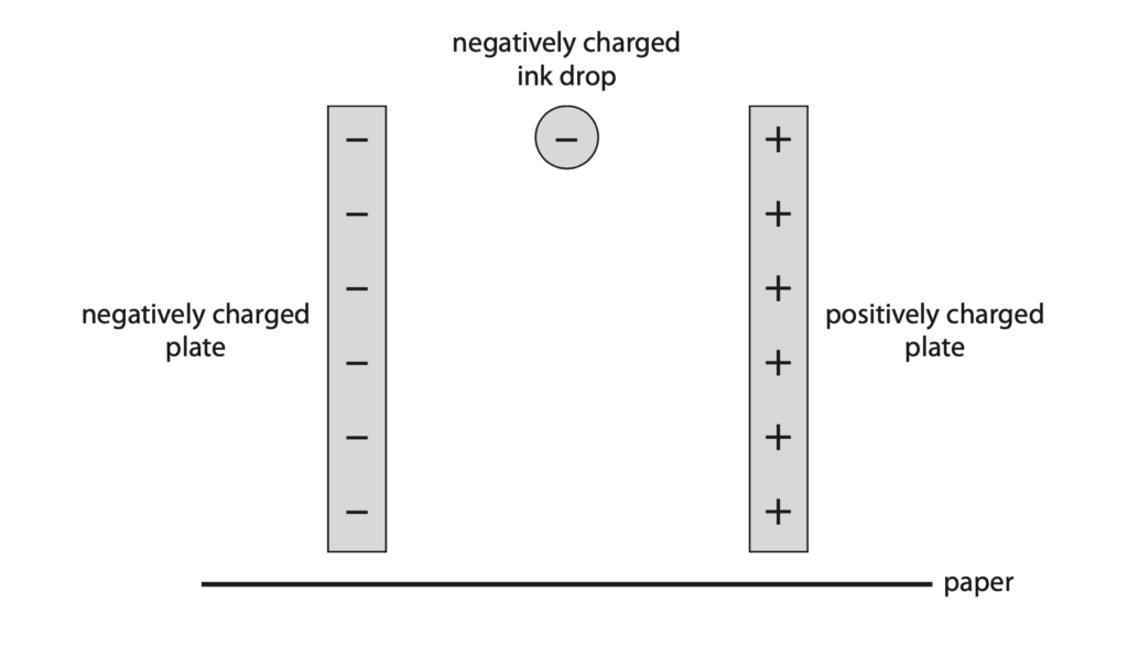
A negatively charged ink drop falls vertically between a pair of charged plates. (a) The ink drop experiences a horizontal electrostatic force as it falls.
Explain the direction of the electrostatic force exerted on the ink drop by the charged plates. (2)
(b) On the diagram, draw the path of the ink drop as it falls between the charged plates until it hits the paper. (2)
(c) (i) The ink drop experiences a horizontal force of 8.5 × 10⁻⁷ N when it is between the charged plates.
The mass of the ink drop is 1.1 × 10⁻¹⁰ kg.
Calculate the horizontal acceleration of the ink drop when it is between the charged plates. (3)
acceleration = …………………………………………………….. m/s2
(ii) The ink drop has no initial horizontal velocity before it passes between the charged plates.
After passing between the charged plates, the horizontal velocity of the ink drop is 3.9 m/s.
Calculate the horizontal distance travelled by the ink drop as it passes between the charged plates.
Give your answer in mm. (4)
distance = …………………………………………………….. mm
d) Explain how another ink drop could be deflected in the opposite direction by a greater distance using the charged plates in the inkjet printer. (2)
(Total for Question 8 = 13 marks)
January 2021 Paper 1PR
12 The diagram shows some apparatus used to find the mass of an object.
The two pieces of metal foil act as a variable resistor.
When more mass is added, the elastic string stretches and the small piece of metal foil moves to the right.
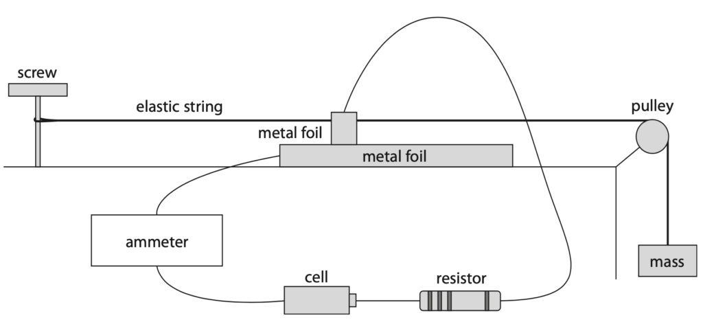
(a) (i) Draw the circuit diagram for this electrical circuit.
The variable resistor has been drawn for you. (4)
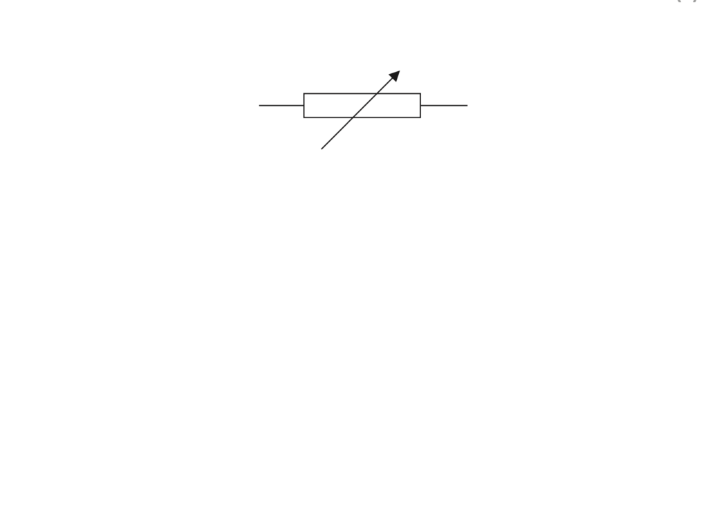
(ii) Draw a voltmeter on the diagram to measure the voltage of the variable resistor. (2)
(b) Explain how the voltage across the variable resistor changes if more mass is added to the end of the elastic string. (4)
(c) The student extends the investigation by keeping the mass constant and replacing the cell with a variable power supply.
The student measures the current in the circuit for different voltages. These are the results.
| Voltage in V | Current in mA |
| 0.0 | 0.0 |
| 2.0 | 4.0 |
| 4.0 | 7.0 |
| 6.0 | 11.0 |
| 8.0 | 14.0 |
(i) State the independent variable in the student’s investigation. (1)
(ii) Plot the student’s results on the grid. (3)
(iii) Draw a line of best fit. (1)

(Total for Question 12 = 15 marks)
2022 Paper 1P
7 A teacher uses this circuit to investigate how the current in a circuit changes with the temperature of a room.
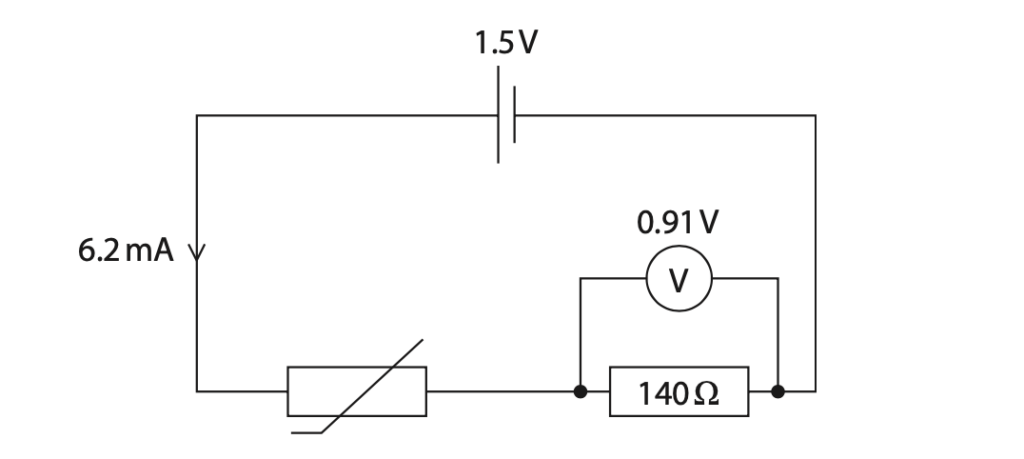
(a) (i) Calculate the voltage across the thermistor. (2)
voltage = …………………………………………………….. V
(ii) State the formula linking voltage, current and resistance. (1)
(iii) Calculate the resistance of the thermistor. (3)
resistance = …………………………………………………….. Ω
(b) The graph shows how the resistance of the thermistor changes with temperature.
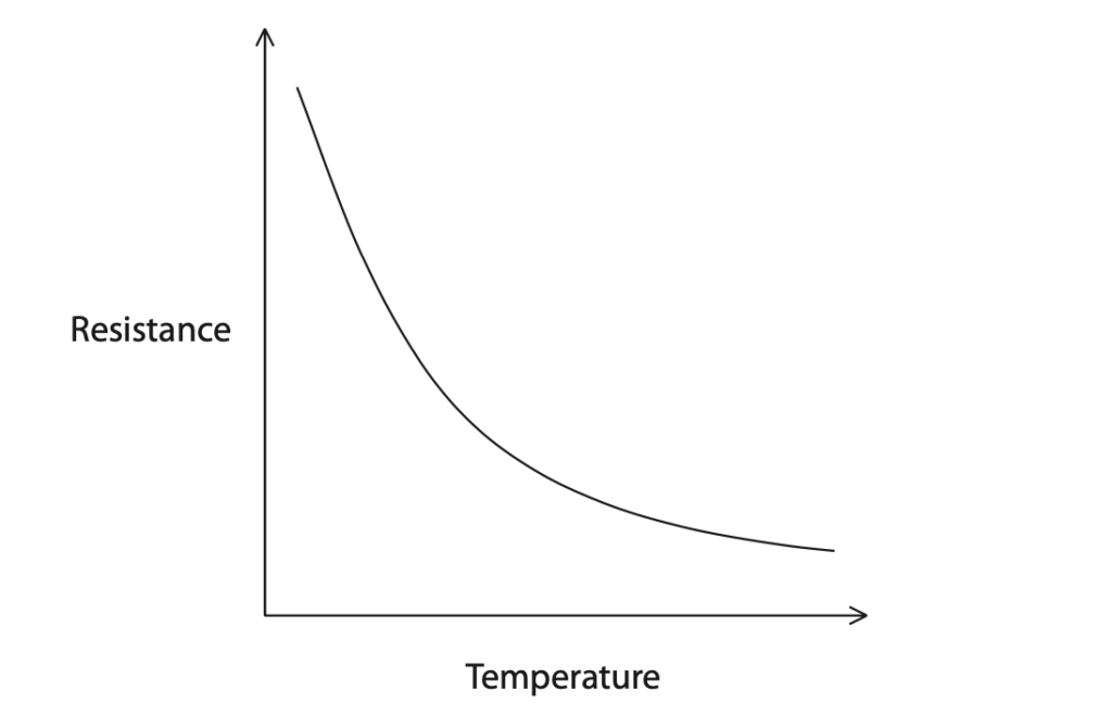
(i) Describe the relationship between the temperature and the resistance of the thermistor. (2)
(ii) Explain how the reading on the voltmeter changes when the temperature of the room decreases. (3)
(Total for Question 7 = 11 marks)
2022 Paper 1PR
9 The diagram shows a circuit containing a cell, two switches and two resistors, R1 and R2 .
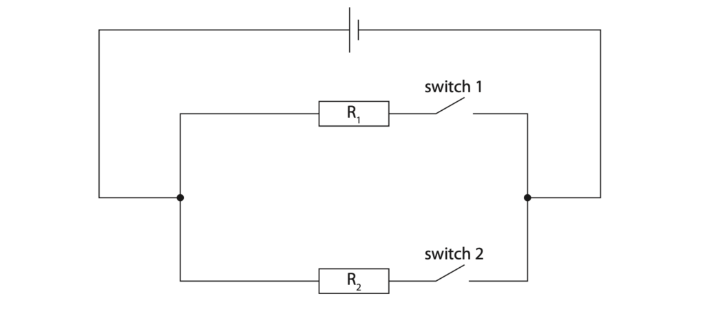
(a) A light emitting diode (LED) is represented using the symbol
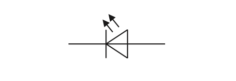
Draw a LED on the circuit diagram that will indicate when there is a current in resistor R1 . (2)
(b) Both switches in the circuit are now closed.
(i) Draw an ammeter on the circuit diagram that will measure the current in the cell. (1)
(ii) The voltage across the cell is 4.5V.
Explain how the voltage across R2 compares with the voltage across the cell. (2)
(c) Switch 1 is now opened whilst switch 2 remains closed.
(i) State the formula linking energy transferred, charge and voltage. (1)
(ii) The voltage across the cell stays constant at 4.5V.
Calculate the charge transferred through the cell when the cell transfers 4.1 J of energy. (3)
charge transferred = …………………………………………………….. C
(iii) A student investigates how the current in resistor R2 varies with the voltage across it.
Describe how the circuit could be modified for the student to do this investigation. (3)
(Total for Question 9 = 12 marks)


